2017 m. gruodžio 18 d., pirmadienis
Here is a French translation of the smd geiger firmware v11.0.2 features description kindly presented by Rémy Rubin from Moutier in Switzerland (Thank you Rémy!)
Here is a French translation of the smd geiger firmware v11.0.2 features description kindly presented by Rémy Rubin from Moutier in Switzerland (Thank you Rémy!):
https://www.dropbox.com/s/ws6jdq5ykb4vcnz/GEIGERmode%20emploi%20Fr%20-firmware%20v11.0.2-.pdf?dl=0
2017 m. rugsėjo 25 d., pirmadienis
Enclosure for 3D printing for geiger with SBT-11 or SBT-11A tube
this is a new modification of the enclosure for SBT-11 / SBT-11A geiger tubes
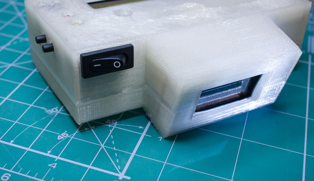
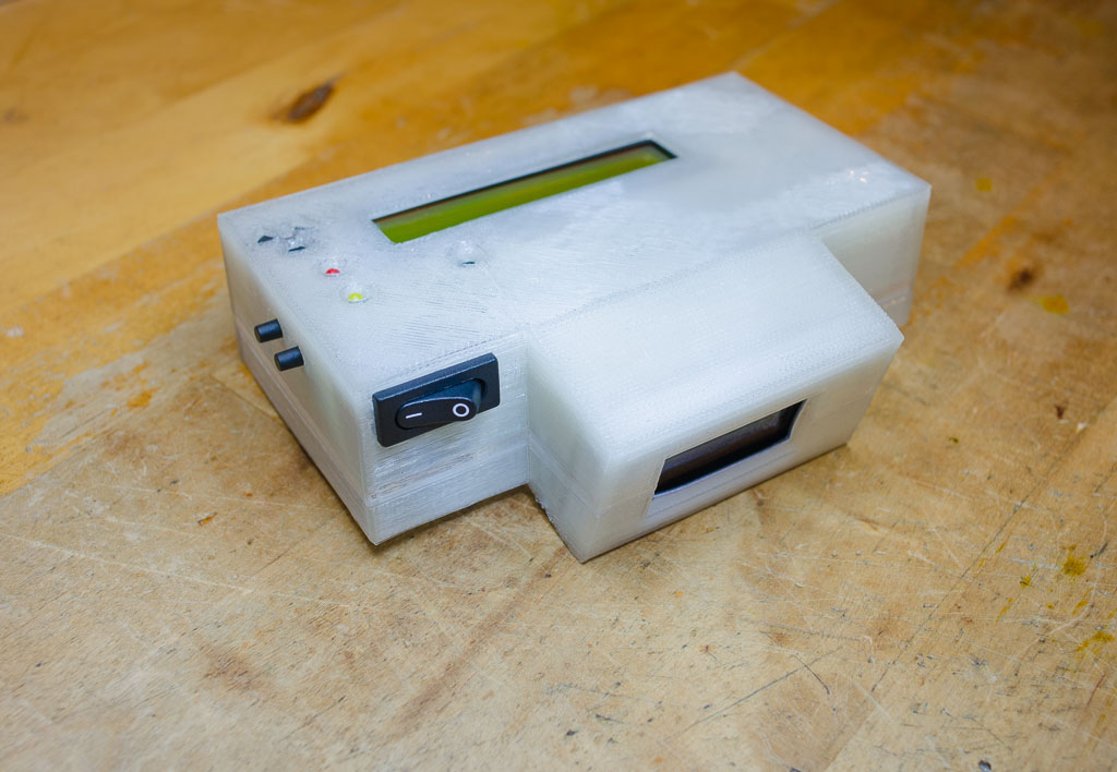
Files can be downloaded for printing from
If you nee the enclosure (just the enclosure with the power button, front protective cap and serial connector openning cap)
you can buy it by pressing on this button here
(note - the shipping price will automatically be presented during the purchase procedure) :
Heres an interesting enclosing solution by Daniel from Czech Republic
Daniel managed to fit everything - electronics, SBT11 pancake tube and even 9V battery in to this small - only 12 cm long enclosure! Wonder how it looks like inside. Thank you for sharing the pictures Daniel!


2017 m. rugsėjo 16 d., šeštadienis
Here's a truly exciting dosimeter-radiometer project with the Arduino IDE compatible easy DIY Geiger nuclear radiation counter kit at its heart by Oleg for your enjoyment
Oleg from Russia, has used the enclosure of the old (hand-dinamo powered) geiger detector DP-62 to build this exquisite almost hermetically sealed and solar rechargable dosimeter/radiometer.
Here are his photos for your enjoyment and stimulation of fantasy, as well as a short Oleg's description in Russian below the pictures:


Здравствуйте!
Наконец, мой проект закончен!
Благодаря Вам теперь у меня есть нормальный дозиметр в, пусть старом, но
добротном и герметичном армейском корпусе ДП-62, теперь не боязно по нашим горам гулять.
Ну хочется похвастаться.
Перепаял все кнопки(вынес наружу), (https://ru.aliexpress.com/item/1PC-Metal-Button-Switch-panel-hole-10MM-2A-36VDC-self-locking-3pin-soldering-IP65/32795709708.html )
Задействовал штатные окошки для самой трубки(закрыто слюдой для бэтты).
Перенёс светодиоды под штатные глазки(под линзой в центре- индикация пролёта гамма-кванта, красный глазок- аларм).
Там же под линзой рядом с жёлтым светодиодом и ИК-диод для настроек с пульта Сони.
Ли-ионник 16340 1000 мА/ч https://ru.aliexpress.com/item/In-stock-2Pcs-Newest-3-7V-1000mAh-CR123A-16340-Li-ion-Rechargeable-Battery-Newest/32754684239.html
, солнечная панель(https://ru.aliexpress.com/item/0-8-Watt-5-5V-solar-panel-Laminate-solar-cells-High-quality-High-Efficiency-2pcs-lot/551858947.html?aff_platform=aaf&cpt=1500412534192&sk=zj6qB6AIM&aff_trace_key=4da50ae661cc483a9b65c1cf60bc089b-1500412534192-07264-zj6qB6AIM), ламинированная полиэтиленом(царапиностойкая),
плата контроллера заряда аккумулятора.https://ru.aliexpress.com/item/6W-5V-UPS-mobile-power-Diy-Board-Charger-Step-up-DC-DC-Converter-Module-for-3/32790658678.html
Панель и кнопки посажены на полиуретановый шовный клей-герметик JetaPro5593.
В пути :
Винт Адаптер Женский 1/4 мужчинами 3/8 для Штатив Монопод
https://ru.aliexpress.com/item/Hot-Convert-Screw-Adapter-Camera-Accessories-of-Female-1-4-to-Male-3-8-for-Tripod/32704353332.html?aff_platform=link-c-tool&cpt=1500412967313&sk=uR7uBY3Rz&aff_trace_key=4e6ffd3a647d4926bc57716372834919-1500412967313-05481-uR7uBY3Rz
Так как сам монопод для использования в режиме поиска на штанге (
https://ru.aliexpress.com/item/Telescoping-Extendable-Stainless-Steel-Monopod-Pole-Handheld-Hold-Grip-Tripod-Mount-Selfie-Stick-for-GoPro/32727991816.html?aff_platform=aaf&cpt=1500413081666&sk=zj6qB6AIM&aff_trace_key=cbc06ab40ea1475ca3d0e02d1d71f275-1500413081666-05625-zj6qB6AIM )
(как ДП-5) уже пришёл
Ну, а Вам, просто спасибо! Я теперь готов к "зомби-апокалипсису" :)
If your Android phone has an iR transmitter you can use this free app from the Android App store with the smd geiger board programmed to work with Sony iR protocol
If your Android phone has a iR transmitter you can use this free app from the Android App store:
When you install this app then download this custom remote file with your phone Internet browser:
and open it (when asked which app to use for opening it choose the app you you have just installed)
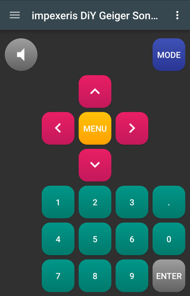
note: the above custom remote file is when firmware which is configured to work with Sony
system remotes uploaded (this is the default configuration of firmware for boards in this listing)
2017 m. rugsėjo 3 d., sekmadienis
A new contact socket for Si-8b (Си-8б), Geiger-Müller tubes
Original contact sockets for Si8b (Си-8б) Geiger-Müller tubes are rather rear and quite expensive.

So here is the 3D printable one. Printed with PLA filament on a 3D printer and equipped with factory made contacts. It has an in-printed marks of Anode (+) and Cathode (-) for easy connection

If you like/need one you can buy it instantly by clicking on this PayPal "Buy Now" button.
2017 m. balandžio 13 d., ketvirtadienis
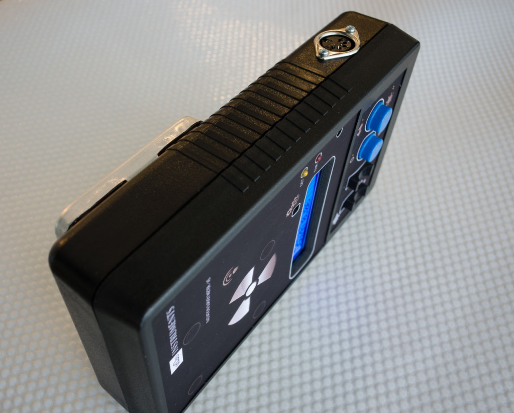
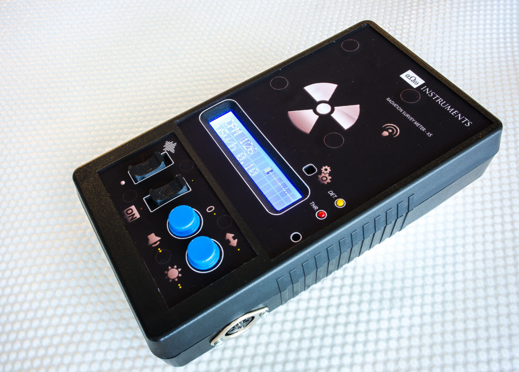
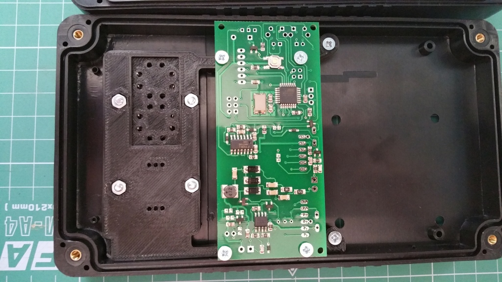
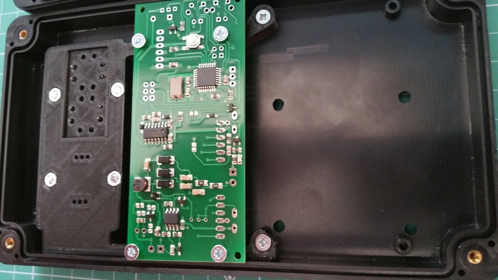
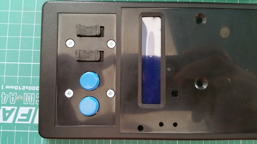
Nuclear Radiation Survey Meter in the factory made quality ABS plastic enclosure for SMD based kits (the direct purchase link inside)
This is an updated enclosure which is designed for the SMD based geiger kit sold on eBay.
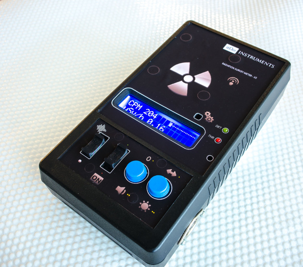
Part list of the Nuclear radiation survey meter shown in the pictures (the one with SBT10A tube):
1 x Electronics kit as on eBay http://www.ebay.com/itm/162026582536?ssPageName=STRK:MESELX:IT&_trksid=p3984.m1555.l2649
1 x factory made enclosure ( available in black or light grey color ) with precisely cut openings for the tube and interface elements
1 x printable vinyl sticker with artwork
2 x microswitches with 3D printed caps
2 x big push-button switches with blue caps
1 x 5 pin socket
1 x 5 pin plug
3D-printed microswitch and push-buttons holder plate
4 x screws for mounting SBT10 tube
4x screws for 3D printed switch holder plate
3D-printed plastic frame for easy mounting of the counter inside the enclosure.
---
If you need the enclosure kit (unassembled and without the electronics) -
Just the enclosure with precise cut-outs, vinyl stickers with artwork, three tumbler switches, one push-button switch, socket and plug connector and internal mounting brackets for the electronics and the tube (tube mounting brackets are only for SBT11 tube kit. Mounting SBT10 and SBT8 tubes don't require such brackets)
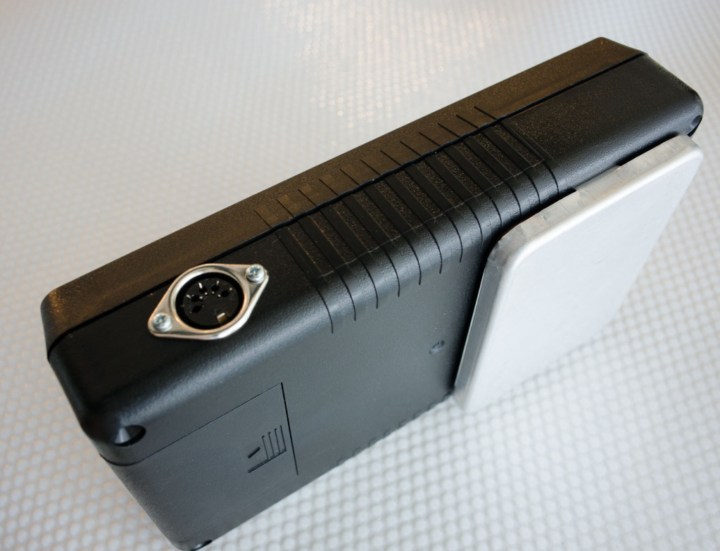
Here below in a video - how the SBT10 tube is installed in this enclosure. Also my advise how to use the aluminium cover if you will be removing it often.
2017 m. kovo 15 d., trečiadienis
Conversion rates for Soviet made Geiger-Müller tubes
There is a compilation of the experimental CPM to uSv conversion factors for Geiger-Müller tubes manufactured at Soviet times. Experimental measurements are done for the natural mix of energies relative to same measurement condition readings of Cs137 calibrated equipment.
Though every tube might have some deviation from such readings most tube's readings give a quite similar results. These numbers do quite well for popular measurements - usually within 1uSv range.
(please kindly comment if you have different data or can challenge the data below in some way as it might help to improve this reference table). As time allows I will be maintaining and adding the data for other tubes.
SBM-20 - conversion factor 220 CPM -> 1uSv/h (working voltage- 400V)
SBM-21 - conversion factor 20.83 CPM -> 1uSv/h (working voltage- 400V)
SI22G - conversion factor 792 CPM -> 1uSv/h (working voltage- 400V)
SBM-19 - conversion factor 928 CPM -> 1uSv/h (working voltage- 400V)
STS-6 - conversion factor 928 CPM -> 1uSv/h (working voltage- 400V)
SBT-9 - conversion factor 150 CPM -> 1uSv/h (working voltage- 400V)
SI-29BG - conversion factor 122 or 112 CPM -> 1uSv/h (depending on batch) (400V)
SBT13 - conversion factor 200 CPM -> 1uSv/h (depending on batch) (380V)
SBT11 - conversion factor 220 or 318 CPM -> 1uSv/h (depending on batch) (390V)
SBT11A - conversion factor 220 or 318 CPM -> 1uSv/h (depending on batch)( 390V)
SBT10 - conversion factor 1250 CPM -> 1uSv/h (380V) (depending on batch)(345V)
SBT10A - conversion factor 1250 CPM -> 1uSv/h (380V) (depending on batch)(345V)
SI8B - conversion factor 1250 CPM -> 1uSv/h (400V)
SI8BM - conversion factor 931 CPM -> 1uSv/h (380V)
Beta-2 - conversion factor 400 CPM -> 1uSv/h (400V)
Beta-1-1 - conversion factor 230 CPM -> 1uSv/h (400V)
2017 m. kovo 5 d., sekmadienis
Cheap but "All-INCLUSIVE ★★★★★" :) solution how to power 5V circuits from rechargeable 18650 battery
Browsing on eBay I have just discovered an excellent cheap and truly "All-INCLUSIVE" solution how to power your 5V circuits from rechargeable 18650 battery so I have decided to tell about it to anyone who gets here to my blog:
The thing looks like this:
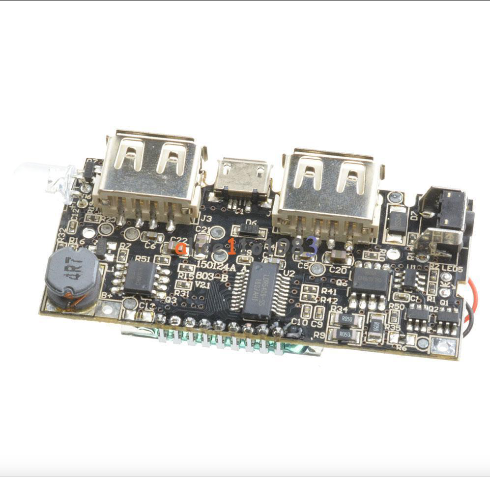
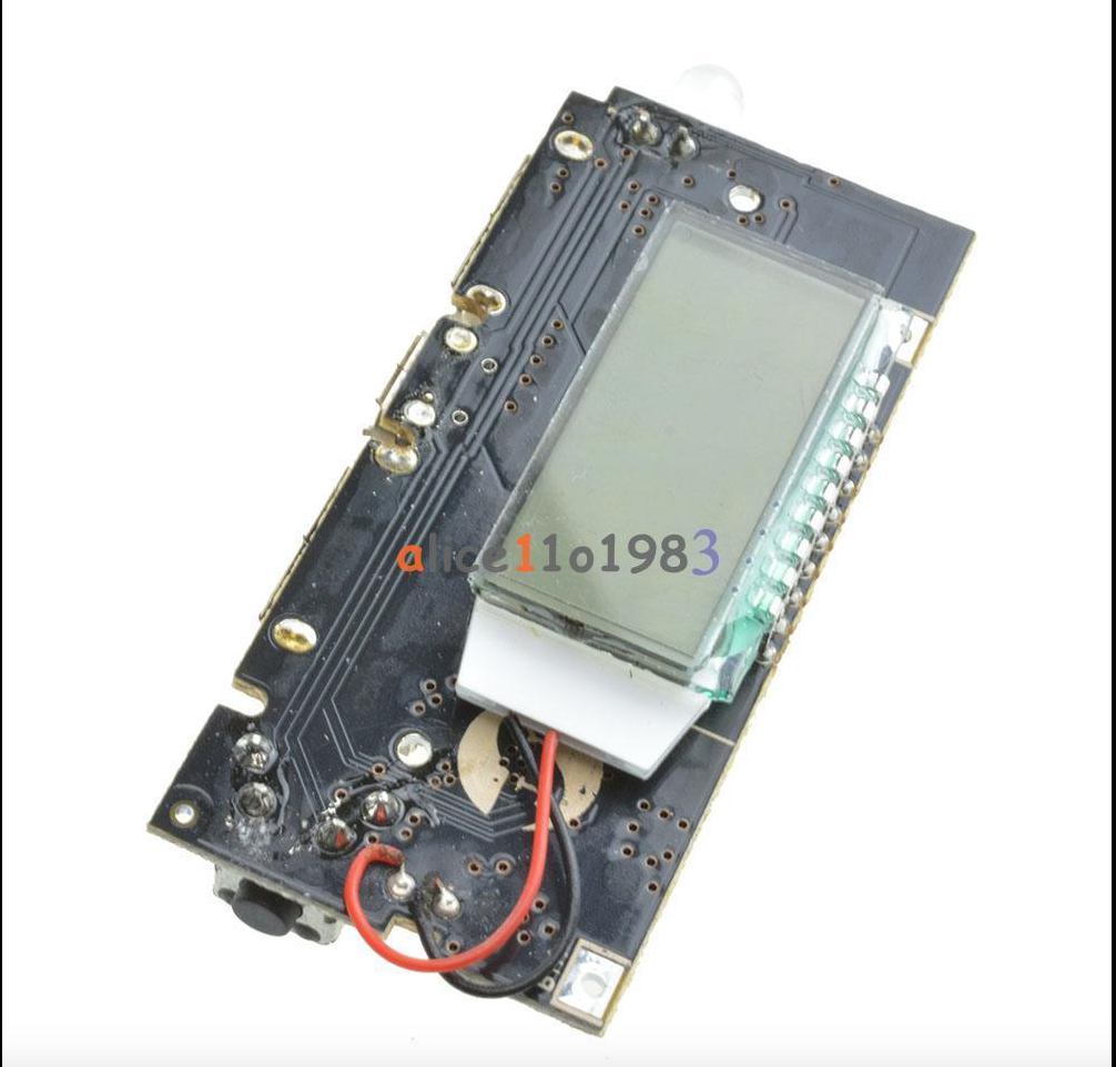
First of all this LDR5409-SS (http://radioskot.ru/_fr/73/LDR5409_Spec_CH.pdf or https://www.dropbox.com/s/gf7exhyvar4no87/LDR5409_Spec_CH.pdf?dl=0 ) module is well designed as it already has secondary battery protection from extreme undercharging (to 2.5V) or overcharging (>4.2V) based on DW01A chip 8205S MOSFET s.
This secondary protection isolates the battery from the rest of the circuit.
The second good thing is that with a little modification this circuit can be used for powering 5V low power devices from the 18650 rechargeable batteries.
Here the main problem with power-bank circuits is, that they monitor load current and if it is lower than ~100mA they decide that the target battery is already charged and it is time for them to get to sleep. So they simply would disconnect your load after a minute or a half a minute.
By removing R41 (see note 1 below) and through the voltage divider between BTA- (the absolutely correct way would be to find the negative point after the battery protection but for the quick test I used BAT-) and BTA+ of total resistance around 500KOhm providing 30mV to the pin 16 (see note 1 below) of the LDR4509 chip. I used a multi-turn 504 (500K) potentiometer with real (measured) resistance of 494,44K preset so that 7.44 was between pin 16 and BTA- while 487K beween pin 16 and BTA+ (no need for being too exact here but approximately R(BTA-)1.5% to 98.5%R(BTA+) ) .When done so, circuit will not be getting to sleep despite low load current and powering down the load. This also helps when power-bank constantly disconnects while the phone is not yet charged (meaning you can charge phones which use low charge current).
!!! So with this you get !!!:
a) secondary 18650 protection from extreme over-charge/over-discharge/over-current so you can use unprotected 18650 batteries which are cheaper to buy or can be salvaged from old notebook assemblies.
b) charger for your 4.2V 18650 rechargeable battery with LCD charge monitor. Which will disconnect the load when battery reaches 2.8V, which is good for battery life.
c) step up inverter from battery voltage to 5V for your low current usage circuit
d) switch which would switch on your circuit by short press of the button and switch off by long hold on the button
e) bright LED flashlight (double click on the button switches it on or off)
The only CON s:
1. when you connect the power source to charge the battery it disconnects your load from the battery. But for a few the price this is miniscule.
2. not sure, but as it is not mentioned in the datas-heet of the LDR5409 it might have no over-temperature protection. But thats is not yet for sure as most popular Chinese charging chips like TP4056 and TP5410 have it.
So here's my test setup:
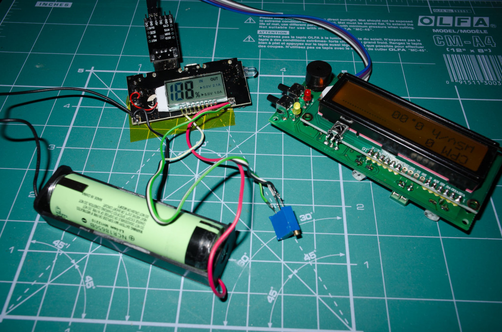

Note1:
LDR5409-SS hip has two current detectors so instead it is possible to remove R41 and connect the middle of voltage divider to pin 18.
UPDATE 1
This is my next modification, where I connect he resistor divider after the immediate battery protection circuit so power (though minuscule around 10μA) is drawn from the already protected battery.
Here below are related videos.
The thing looks like this:
This secondary protection isolates the battery from the rest of the circuit.
The second good thing is that with a little modification this circuit can be used for powering 5V low power devices from the 18650 rechargeable batteries.
Here the main problem with power-bank circuits is, that they monitor load current and if it is lower than ~100mA they decide that the target battery is already charged and it is time for them to get to sleep. So they simply would disconnect your load after a minute or a half a minute.
By removing R41 (see note 1 below) and through the voltage divider between BTA- (the absolutely correct way would be to find the negative point after the battery protection but for the quick test I used BAT-) and BTA+ of total resistance around 500KOhm providing 30mV to the pin 16 (see note 1 below) of the LDR4509 chip. I used a multi-turn 504 (500K) potentiometer with real (measured) resistance of 494,44K preset so that 7.44 was between pin 16 and BTA- while 487K beween pin 16 and BTA+ (no need for being too exact here but approximately R(BTA-)1.5% to 98.5%R(BTA+) ) .When done so, circuit will not be getting to sleep despite low load current and powering down the load. This also helps when power-bank constantly disconnects while the phone is not yet charged (meaning you can charge phones which use low charge current).
!!! So with this you get !!!:
a) secondary 18650 protection from extreme over-charge/over-discharge/over-current so you can use unprotected 18650 batteries which are cheaper to buy or can be salvaged from old notebook assemblies.
b) charger for your 4.2V 18650 rechargeable battery with LCD charge monitor. Which will disconnect the load when battery reaches 2.8V, which is good for battery life.
c) step up inverter from battery voltage to 5V for your low current usage circuit
d) switch which would switch on your circuit by short press of the button and switch off by long hold on the button
e) bright LED flashlight (double click on the button switches it on or off)
The only CON s:
1. when you connect the power source to charge the battery it disconnects your load from the battery. But for a few the price this is miniscule.
2. not sure, but as it is not mentioned in the datas-heet of the LDR5409 it might have no over-temperature protection. But thats is not yet for sure as most popular Chinese charging chips like TP4056 and TP5410 have it.
So here's my test setup:
Note1:
LDR5409-SS hip has two current detectors so instead it is possible to remove R41 and connect the middle of voltage divider to pin 18.
UPDATE 1
This is my next modification, where I connect he resistor divider after the immediate battery protection circuit so power (though minuscule around 10μA) is drawn from the already protected battery.
Here below are related videos.
UPDATE 2
Have checked how long the Panasonic unprotected NCR18650B 3400 mAh battery powers the geiger counter.
With LCD backlight on it worked over 17 hours. Without the LCD backlight - around 28 hours.
Charging from 0% to 100% took 2.5 hours. Note that not full capacity of the battery is used in order to keep it healthy for long time.
So far looks nice.
Užsisakykite:
Pranešimai (Atom)